· 4 min read
Gamma-ray Transients Monitor (GTM)
Gamma-ray Transients Monitor (GTM) is on-board Formosa-8B (FS-8B) and monitor cosmic gamma-ray transients. Main targets are various, such as Gamma-ray bursts (GRBs), solar flares and magnetar bursts.
The satellite FS-8B is designed by Taiwan Space Agency (TASA). FS-8B is scheduled to launch into a low-altitude (561 km), high-inclination (97.64°), sun-synchronous Earth orbit in 2026. GTM is the science payload of FS-8B. Its power and mass budget is 2 W (orbital average) and 2 kg, respectively. GTM will operate only when the remote sensing payload is off. The expected GTM operation duty cycle is about one third.
Though GTM is smaller than other Gamma-ray telescopes, it can cover nearly all sky to monitor GRBs and measure the location of a single event independently. This enhances more confirmed detection of GRBs with other missions. We made a compare between GTM and other gamma-ray monitors in Table. 1.
| Parameter | GTM | Fermi/GBM |
|---|---|---|
| Total mass (kg) | 1.9 | 115 |
| Material | GAGG | Nal |
| Number of detector | 8 | 12 |
| Area (cm^2) | 25 | 126 |
| Thickness (cm) | 0.8 | 1.27 |
| Energy range (keV) | 50-2000 | 8-1000 |
Payload and the Bus
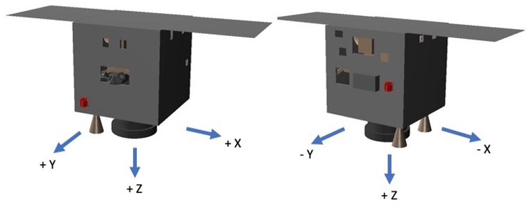
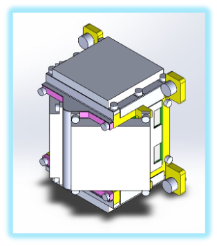
GTM is composed of two opposite models on +y (the primary one) and -y (the secondary one) sides of the spacecraft bus, as shown with the two red boxes in the Fig. 1. The modules are 10 cm with the length and width, and 8 cm with the thickness. Fig. 2 shows that there are 4 sensors with distinct facing directions in each module to cover the all sky events.
Total 8 units altogether provide 4π FoV and includes all the directions. The sensor units consist of the major scintillator arrays with 16 channels, and employed Gadolinium Aluminum Gallium Garnet (GAGG) as the material. Compared with other materials, GAGG shows large density of 6.63 g/cm3, adequate light yield about 56,000 photons/MeV, decay time about 100 ns, and acceptable energy resolution about 6% at 662 keV. Besides, GAGG is not hygroscopic.
Sensors and Detectors
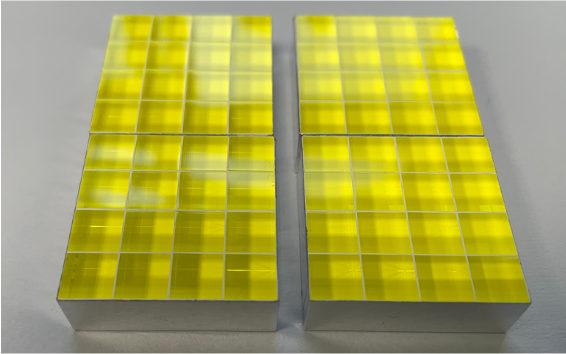
The scintillator array is composed of four sub-arrays, as shown in Fig. 3. One sub-array consists of 16 GAGG bars, 6 mm × 6 mm × 8 mm each, in a 4 × 4 configuration to form 16 pixels with 6 mm × 6 mm in size for a pixel. Each GAGG bar is surrounded with 0.2-mm-thick BaSO4 on the top and the four long sides as the scintillation-light reflection layers. Each sub-array is wrapped with a 0.05-mm aluminum film on the top and four sides. At the bottom of the sub-array, an SiPM of the same pixel size (Hamamatsu S13361-6050NE-04) is attached to convert scintillation light to electrical signals. Four sets of GAGG sub-arrays with SiPM are put together on a PCB for electrical signal output. The sensor unit is enclosed in an aluminum cover of 1-mm thickness on the top and 2-mm on the four sides. A thermal pad of thickness about 0.38 mm (Parker Chomerics 1671) is inserted between the GAGG array and the aluminum cover. The aluminum cover is part of the whole mechanical structure of the module.
Instrument Performance
We simulate the effective area with face-on observation (photons from the on-axis source) of one GTM sensor unit. The method is Monte Carlo simulation, and we run the simulations conducted with a Geant4-based simulation toolkit, the Medium Energy Gamma-ray Astronomy Library (MEGAlib; Zoglauer et al. (2008)). The interactions can be identified as absorption, photon scattering, pair production or hits on the passive material. (Fig. 4)
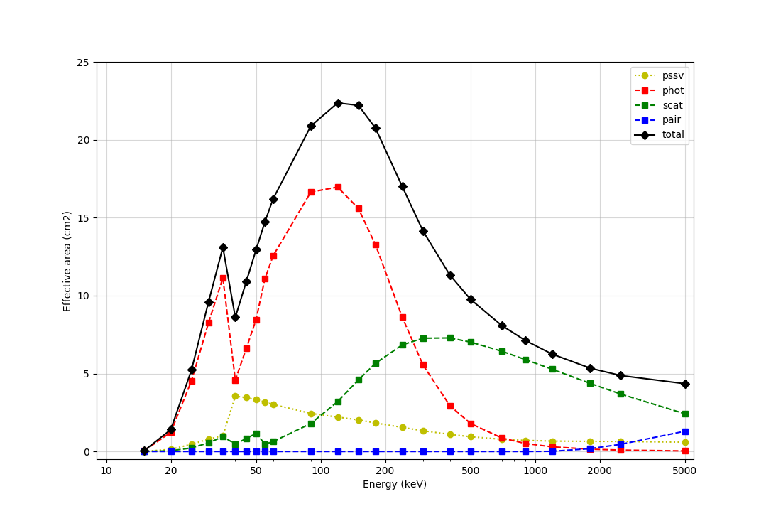
The effective area in the low energy end is suppressed at about 15 keV, since the passive material equipped below the scintillators shield out the low energy photons. The 1- statistical uncertainties are 0.1%, which show smaller than the symbol size in the figure. We ideally define 15 keV as our energy threshold, though there may be a peak at 35 keV for the presence of Ba from BaSO4. For this result, we can take the 35- keV peak as a on-board calibrator. We setup the sensitivity of GTM from 15 keV to 2 MeV. In this energy range, GTM can detect ~40 GRBs per year, provide the prompt notice and later information (e.g. light curve, spectrum) to people.
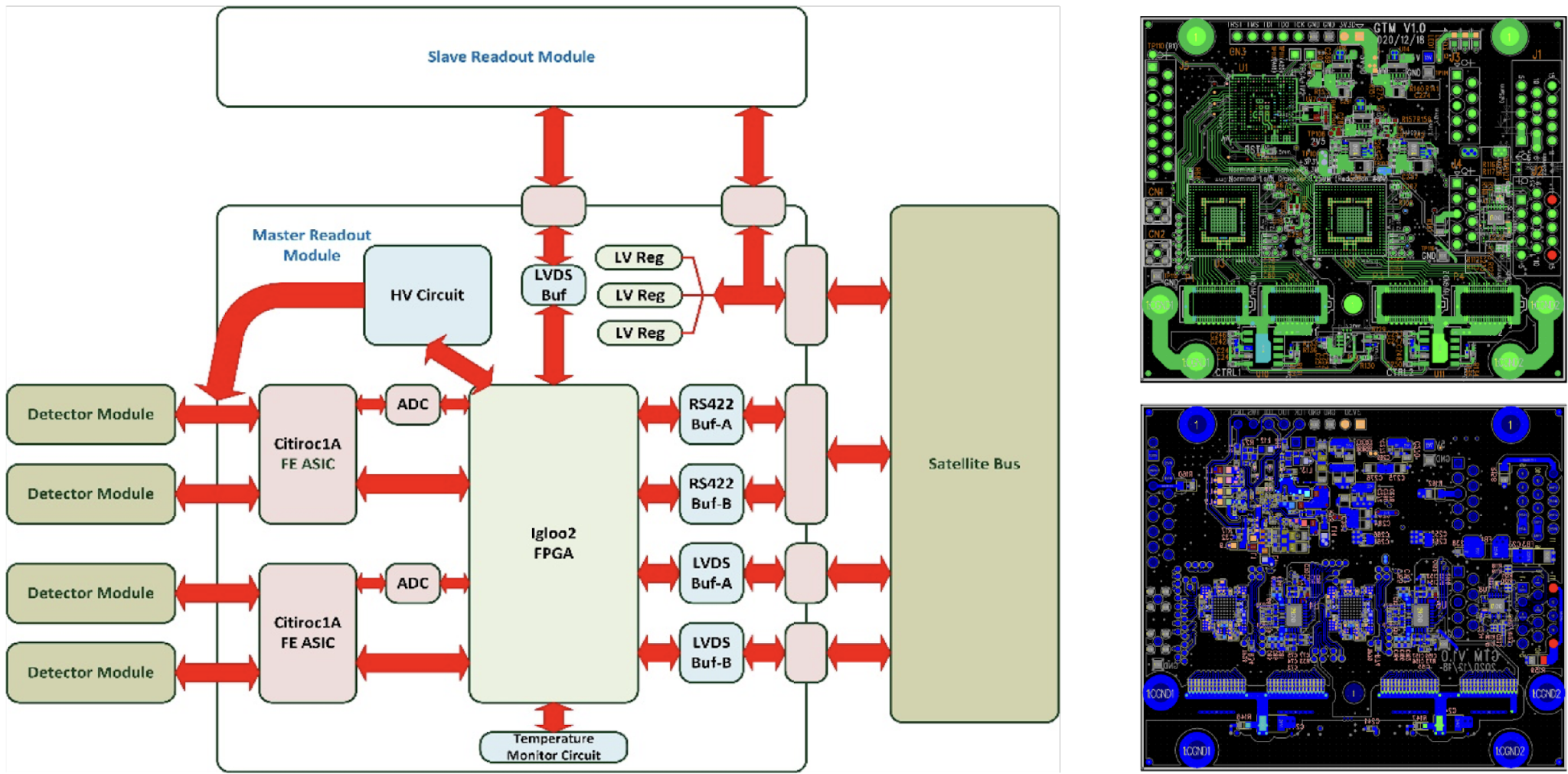
Schematic
Fig. 5 is the GTM’s triggering scheme. The two modules are connected with each other, and the primary one is connected to the bus. Both the modules are with the same design.